Overview
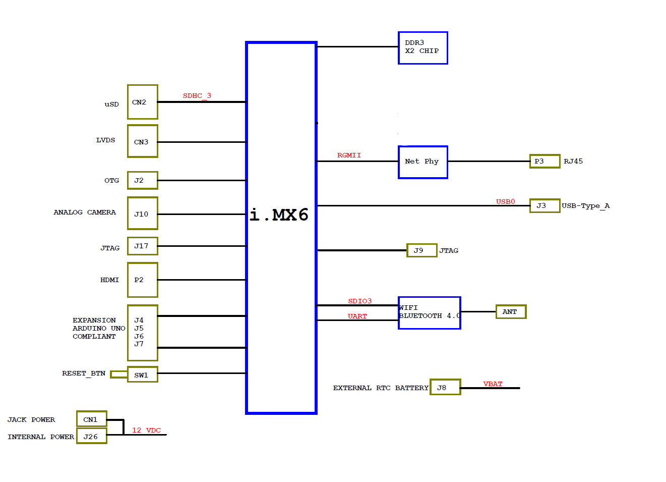
i.MX 6SoloX embeds on a single chip a single core ARM Cortex A9 and a ARM cortex M4 microcontroller.
For any deep inquiry regarding i.MX 6SoloX, please have a look at the dedicated reference manual made by Freescale.
They can use and share lot of hardware implemented features provided by the architecture as:
- GPIOs
- UARTs
- I2Cs
- SPIi
- analogs ADCs
These two processors are connected to all interfaces and peripherals through an high speed AXI bus. It’s up to the programmer or the "system" admin to define witch features are assigned to each processors.
All the hardware features block can be accessed and connected via processors pad with a editable muxing. So the functions are not fixed but can accessed on different pads. Some of these pads are connected to external pins to allow the users to connect their stuff.
External pins (orange) are by default assigned to A9 in GPIO mode. So these pins can be controlled directly from the file system (Linux, Android). Internal pins (blue) are assigned and controlled by Cortex M4 with the same dimensions of Arduino UNO pinout. All the Arduino shields compatible can be plugged directly on UDOO Neo board.
Pinout Available features
I.MX 6SoloX provides the following functions, part of them are fully available on the pinout.
Hardware features
In the following tables are listed all the functional block with relative signals and pin numbers. In some cases the same signal are available in more then one pin.
UART serial ports
| PORT | Signal Name | Internal Pin | External Pin | |
|---|---|---|---|---|
| UART1 | UART1_TX_DATA | 47 | ||
| UART1_RX_DATA | 46 | |||
| UART2 | UART2_TX_DATA | 45 | ||
| UART2_RX_DATA | 44 | |||
| UART3 | UART3_TX_DATA | RESERVED FOR BLUETOOTH CHIP | ||
| UART3_RX_DATA | RESERVED FOR BLUETOOTH CHIP | |||
| UART5 | UART5_TX_DATA | 0 | ||
| UART5_RX_DATA | 1 | |||
| UART6 | UART6_RI_B | 40 | ||
| UART6_DSR_B | 39 | |||
| UART6_DTR_B | 38 | |||
| UART6_DCD_B | 37 | |||
| UART6_RX_DATA | 36 | |||
| UART6_TX_DATA | 35 | |||
| UART6_RTS_B | 34 | |||
| UART6_CTS_B | 33 |
I2C
| PORT | Signal Name | Internal Pin | External Pin | |
|---|---|---|---|---|
| I2C1 | I2C1_SCL | 26 | ||
| I2C1_SDA | 27 | |||
| I2C2 | I2C2_SCL | 36 | 14 - SCL | |
| I2C2_SDA | 37 | 15 - SDA | ||
| I2C3 | I2C3_SCL | RESERVED FOR LCD / HDMI | ||
| I2C3_SDA | RESERVED FOR LCD / HDMI | |||
| I2C4 | I2C4_SCL | 32 | 34 | |
| I2C4_SDA | 33 | 35 |
CAN
| PORT | Signal Name | Internal Pin | External Pin | |
|---|---|---|---|---|
| CAN1 | CAN1_RX | 40 | ||
| CAN1_TX | 41 | |||
| CAN2 | CAN2_RX | 42 | ||
| CAN2_TX | 43 |
PWM - Pulse Width Modulation
| PORT | Signal Name | Internal Pin | External Pin | |
|---|---|---|---|---|
| PWM1 | PWM1_OUT | 3 | ||
| PWM2 | PWM2_OUT | 4 | ||
| PWM3 | PWM3_OUT | 16 | 5 | |
| PWM4 | PWM4_OUT | 17 | 6 | |
| PWM5 | PWM5_OUT | 30 | 7 | |
| PWM6 | PWM6_OUT | 31 | 9 | |
| PWM7 | PWM7_OUT | 11 | ||
| PWM8 | PWM8_OUT | 10 |
CSI - Camera
| PORT | Signal Name | Internal Pin | External Pin | |
|---|---|---|---|---|
| CSI1 | CSI1_VSYNC | 24 | ||
| CSI1_HSYNC | 25 | |||
| CSI1_DATA02 | 26 | |||
| CSI1_DATA03 | 27 | |||
| CSI1_DATA04 | 28 | |||
| CSI1_DATA05 | 29 | |||
| CSI1_DATA06 | 30 | |||
| CSI1_DATA07 | 31 | |||
| CSI1_DATA08 | 32 | |||
| CSI1_DATA09 | 33 |
SPI
| PORT | Signal Name | Internal Pin | External Pin | |
|---|---|---|---|---|
| ECSPI2 | MISO | 20 | ||
| MOSI | 21 | |||
| SCLK | 38 | |||
| SS0 | 39 | |||
| ECSPI3 | MISO | 18 | A1 | |
| MOSI | A0 | |||
| READY | ||||
| SCLK | A4 | |||
| SS0 | A5 | 19 | ||
| SS1 | 21 | |||
| SS2 | 22 | |||
| ECSPI5 | MISO | 40 | ||
| MOSI | 43 | |||
| SCLK | 42 | |||
| SS0 | 41 |
 UDOO Neo Documentation
