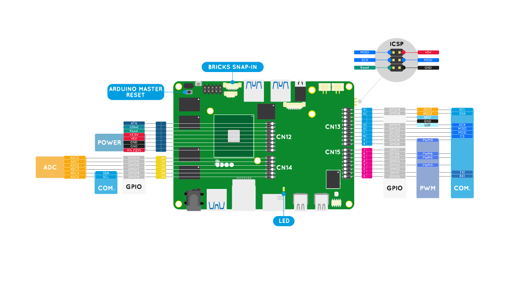
Pinout
The embedded Arduino 101 input/output (I/O) pins operate at 3.3 V, with a maximum 20 mA DC current per pin. They are located on the inner columns of the dual headers.
The I/O voltage of 3.3 V is lower than the older Arduino UNO's 5 V. Keep this in mind when using shields and modules – Make sure you have set these accessories to operate at 3.3 V, which is typically performed by setting a jumper, a switch, or solder pad bridge (refer to the documentation of your shield/module for details). The I/O of the Arduino 101 is 5 V tolerant, therefore, if a shield/module is incorrectly set to 5 V, you will fortunately not damage the Arduino.
Be attentive when copying circuits from example diagrams that use a 5 V I/O. Make sure to adjust for the lower I/O voltage of the Arduino 101 where appropriate. This may include recalculating resisters using Ohm's Law for the components like LEDs. For guidance, please see the example project section of this documentation, or head to the UDOO forum to post any questions that you might have.
All the digital pins can have interrupts attached - A significant increase over the two interrupt capable pins on the Arduino™ UNO. An interrupt is an advantageous way of making code execute in response to abrupt input changes, for example, a rotary encoder being adjusted.
There are six analog input pins at 10-bit resolution, providing a range of 1024 values between ground and 3.3 V. The number of inputs and resolution can be increased if required, by using an external ADC module.
Analog output is simulated using pulse width modulation (PWM) on digital pins 3, 5, 6 and 9. For an explanation of PWM, refer to the following Arduino tutorial
Arduino™ Shields compatibility
Here you can find a very useful document by Intel® regarding the compatibility of shields made for Arduino™ with the Intel® Curie™-based Arduino™ 101 board.
Shield Testing Report for the Arduino 101* Board
Heads up! As you can see from the image on top of the page the ICSP/SPI connector proper of the Arduino™ Pinout is moved to the bottom side of the UDOO X86 board. If you need to use a shield that communicates through this connector you need to connect the pins accordingly.
UDOO BRICKs Snap-in
The UDOO X86 features a BRICKs Snap-in connector to use UDOO BRICKs sensors connected to the Intel® Curie™-based Arduino™ 101 side of the board.
Check the Bricks snap-in sensors page to know how to use the sensors in Arduino™ programming.